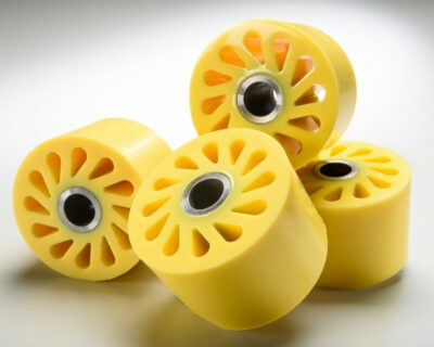
An engineer at a company wanted to know if we could create convex urethane rollers for a special type of machine the company was building. What made these rollers unique were the cores – the customer wanted them to have a convex shape.
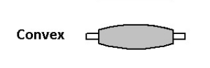
We do manufacture convex rollers, but usually the roller cover itself is convex and the core is straight – as it appears in the sketch below.
Creating a convex core sounded exciting because we would have to figure out how to create the urethane cover cost effectively. We could have done a convex mold, but that would require a split mold.
A split mold meant the cover would have a seam, and the seam would then need to be machined. Since this was a relatively high-speed roller, and concentricity – or vibration – was a big concern, the split mold was a less attractive option. (A seam on a high-speed roller can cause vibration, so we like to avoid seams if possible.)
In addition to our already substantial chemical bond, the customer also wanted a mechanical bond to ensure for the urethane cover wouldn’t delaminate during use.
And, last but not least, we would need to press a special type of bearing housing into the ends of each roller.
Step #1: Choosing the right material
UI first worked with the customer to determine the correct durometer for the urethane cover based on the customer’s application requirements.
A harder durometer was chosen based on application speed and load, as well as to provide the longest life.
Another reason for choosing a hard durometer urethane is because it’s quite difficult, and time-consuming, to machine a softer durometer convex surface to meet tight tolerances – in this case, +/- .005.
Step #2: Create the machined cores with grooves
Based on the customer’s drawings, UI created the aluminum cores at our in-house machine shop. Each end of the core accommodates a pressed-in bearing housing. The inner diameter of the core is for the machine shaft to pass through.
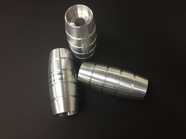
Why the four grooves? Before we cast urethane to cores or hubs, we apply a chemical process, which then creates a bond between the cover and the core.
The customer, however, wanted both a chemical and mechanical bond. When the urethane material is poured, it fills the grooves and makes a very tight mechanical bond – thus enhancing our substantial chemical bonding process. Both the mechanical and chemical bonds help reduce the potential for failure or slippage.
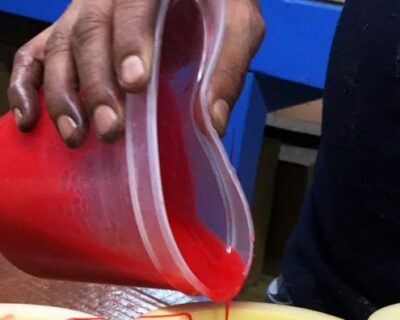
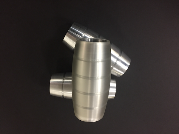
Step #3: Cover the cores
In the next two photos, you can see the cover on one of the cores. The urethane covers for the customer are actually black; we did this one in clear urethane so you could see the core underneath.
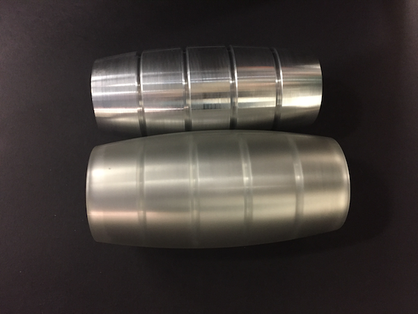
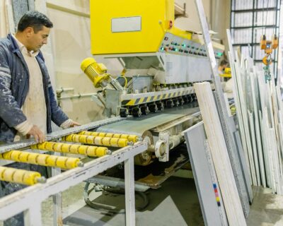
Step #4: Machine the convex surface of the urethane cover
To ensure the rollers run true, and to meet the customer’s specifications, the urethane covers were then machined. This process also makes the urethane nice and smooth.
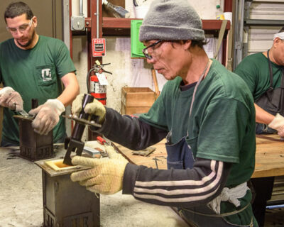
Step #5: Press in the bearings
Since the rollers are for a prototype application, the customer provided proprietary bearings, which UI craftsmen pressed in to ensure the proper fit.
Bearing fit is crucial: if they’re not fitted properly, the roller can run untrue and build up heat. This heat build up can damage the cover or cause vibration in the customer’s machine.
Once the bearings were pressed in, the rollers were inspected by QA and then shipped off to the customer.
Since these are prototype rollers, the customer will run various tests and provide feedback. Based on the feedback, we’ll then make any final tweaks in preparation for future production runs.
These convex rollers are just another way we help solve customers’ unique challenges. Whether you need help from the prototype stage to final production runs, we can help you save costs and improve part performance. Just ask!